• RAD Blog

RAD Electrical Services

Electrician in Denver, Colorado

  • About Us
  • Products and Services
  • Gallery
  • Contact Us

Low voltage

· by Randy ·

Understanding voltage drop is the key to a successful low voltage lighting design.

With the rising popularity of residential and commercial landscape lighting, end-users and homeowners have begun looking for systems and components that combine easy installation and adequate safety considerations in one package. Standard 120V systems are unable to meet these requirements, so the industry’s landscape lighting manufacturers have responded by adopting 12V low voltage systems as the standard for outdoor applications. Low voltage systems use smaller light sources, are easy to modify to accommodate changes in landscape layout, and are safer to operate and maintain than their 120V counterparts.

In standardizing the 12V low voltage system, manufacturers have made available various sizes of step-down transformers to convert a standard 120V source to a 12V supply. The components of the system may be easier to work with, but voltage drop must be considered and understood to effectively service the customer’s landscape lighting needs. Depending on its size and length, the conductor serving the fixtures of a low voltage lighting system acts as a resistor. As current runs through the conductor, a voltage drop occurs; the voltage at the end of the conductor is lower than at the source. Smaller wires and higher currents will increase the voltage drop by raising resistance and increasing the fixture load respectively.

Why worry about it? Voltage drop on a lighting circuit in a 12V system isn’t considered a major issue. The branch circuit currents are relatively low- usually 20A or below- and the standard wire sizes are usually large enough to minimize resistance problems. When working with 12V systems, however, the line current for any given load increases by a factor of 10. For example, a 100W 120V incandescent lamp draws .83A, but an equivalent load of two 50W MR16 12V lamp draws 8.3A. If you use the same size and length wire in both systems, the voltage drop in the 12Vsystem will be 10 times greater than in the 12V system. In this case, voltage drop becomes a significant consideration. When the actual voltage delivered to a given incandescent lamp is lower than the lamp’s rated voltage, the light output will be reduced. This relationship isn’t linear. When the voltage decreases to about 85% of its rated value, the visible light output is only about 50%. It continues to drop quickly from this point forward.

How to minimize voltage drop. Once you’ve finalized the lighting layout, you can control voltage drop by selecting the most effective gauge wire. The smaller gauge, the less the voltage drop. A minimum light output of 50% for the last fixture on a given run is normally an acceptable limit.

Many transformers have multiple taps on the low voltage side of the unit that provide 12V, 13V and 14V output. Using a higher voltage tap to offset the expected voltage drop helps maintain the desired light output by delivering a closer-to-rated voltage at the remote lamps. This technique is used primarily where the distance to the first fixture is a long way from the transformer. Take care to avoid providing an over-voltage situation to the first grouping of fixtures, as this would shorten the lamps’ life.

You can also minimize voltage drop by altering your cable layout design. There are several options you can use other than a straight run:

  • Multiple straight runs can be made in several directions. Tee connections reduce voltage drop by using heavier gage cable for the primary feed.
  • A loop design reduced voltage drop and allows the lighting units to give off a more uniform light output. It’s important to match the wire polarity at the transformer connection in a loop layout.
  • Locating several smaller transformers closer to the end of your cable runs can also help limit voltage drop. If at all possible you should center the transformer in the run. If the light fixtures are located too far from the 120V source, consider running a 120V feed to a transformer located closer to the low voltage lighting fixtures.

If you’re only trying to serve a few limited fixtures, consider using direct burial, 12V transformers for each fixture, which can be fed with a 120V source. Another way to minimize voltage drop is to use lower voltage lamps in your design. For example, 18W lamps are the preferred choice for spread lights, but you can also use 12W lamps. If you decide to use lower wattage lamps, however, recheck your photometric levels so you don’t wind up with an inferior lighting design.

Trouble shooting- Low voltage lighting installations require a great deal of care during installation due to the high currents in the system. Placing too many fixtures on the circuit or using the wrong wire size can lead to a system overload. Therefore, it’s important to troubleshoot the system after installation.

The most common problems encountered in low voltage landscape lighting installations are poor wire connections, too many fixtures on one transformer (overloading), and cables that are too small for the load. By understanding voltage drop, you can address these problems and implement a successful low voltage lighting design. Low voltage lighting will allow the end-user to change the landscape layout and ensure safe outdoor lighting.

Filed Under: RAD Blog ·

Arc Faults

· by Randy ·

Problems in home wiring, like arcing and sparking, are associated with more than 40,000 home fires each year. These fires claim over 50 lives and injure 1,400 victims annually. A new electrical safety device for homes, called an arc faults circuit interrupter or AFCI, is expected to provide enhanced protection from fires resulting from these unsafe home wiring conditions.

Typical household fuses and circuit breakers do not respond to early arcing and sparking conditions in home wiring. By the time a fuse or circuit breaker opens a circuit to defuse these conditions, a fire may have already begun.

Several years ago, a CPSC study identified arc fault detection as a promising new technology. Since then, CPSC electrical engineers have tested the new AFCIs on the market and found these products to be effective.

Requiring AFCIs

AFCIs are already recognized for their effectiveness in preventing fires. The most recent edition of the National Electrical Code, the widely-adopted model code for electrical wiring, will require AFCIs for bedroom circuits in new residential construction, effective January 2002.

Future editions of the code, which is updated every three years, could expand coverage.

AFCIs VS. GFCIs

AFCIs should not be confused with ground fault circuit interrupters or GFCIs. The popular GFCI devices are designed to provide protection from the serious consequences of electric shock.

While both AFCIs and GFCIs are important safety devices, they have different functions. AFCIs are intended to address fire hazards; GFCIs address shock hazards. Combination devices that include both AFCI and GFCI protection in one until will become available soon.

AFCIs can be installed in any 15 or 20-ampere branch circuit in homes today and are currently available as circuit breakers with built-in AFCI features. In the near future, other types of devices with AFCI protection will be available.

Should you install AFCIs?

You may want to consider adding AFCI protection for both new and existing homes. Older homes with ordinary circuit breakers especially may benefit from the added protection against the arcing faults that can occur in aging wiring systems.

Be sure to have a qualified electrical install AFCIs; do not attempt this work yourself. The installation involves working with electrical panel boxes that are usually electrically live, even with the main circuit breakers turned off.

Filed Under: RAD Blog ·

Surge Suppressors

· by Randy ·

You’re at your home computer when suddenly the lights flicker, your computer screen fades to black; then a copy is restored. Sound familiar you’ve just experienced a power surge. Power surges—also known as transient voltage surges—are brief spikes of power that can travel through power lines. Power surges can permanently damage computers, televisions, fax machines and other home appliances that contain microprocessors and sensitive electronic components.

Many people assume that surge suppressors can protect their home from lightning damage. Surge suppressors are not lightning protection devices- they cannot protect your home or you home’s internal electrical wiring from a direct strike. Surge suppressors can, however, protect your equipment from voltage surges caused by unexpected occurrences such as a utility pole downed by a storm. Surges can also generate from inside the home. For instance, appliances such as furnaces, air conditioners and vacuum cleaners can cause power surges in your home’s electrical system when turned on or off. In some cases, remote lightning strikes can cause surges. However, UL Listed Transient Voltage Surge Suppressors (TVSS) can reduce the risk of such damage.

The unpredictable nature of surges makes it difficult to suppress them; you never know when, how long or how powerful they will be. In some cases, a surge may have a higher energy level than the device can handle. When this happens, the surge suppressor may be damaged and lose its ability to provide protection against future surges.

Some surge suppressors look very similar to multiple-outlet power strips but obviously have additional features to suppress surges. Other surge suppressors resemble common plug-in adapters. Not all power strips and adapters offer surge suppression, so make sure the product and product packaging clearly states “UL Listed Transient Voltage Surge Suppressor.”

Filed Under: RAD Blog ·

Contact Us

· by Randy ·

Hours of operation

Moday-Friday: 7:30am-4:30pm

Saturday: 9am-3pm

Sundays: Closed

Phone number- 303-349-2126

You can use this form to contact us and we will get in touch with you right away!

RAD Electrical has been serving northern Colorado since 2008. A young and energetic company, we strive to provide you with the most comprehensive and professional service possible. We are fully licensed, insured and knowledgeable in many areas including; remodeling, indoor/outdoor electrical work upgrades and repairs, new construction, home additions and more.

Filed Under: Contact Us ·

Fire Protection

· by Randy ·

Few of us realize how easily—and how quickly—fire can destroy our homes and take the lives of those we love. Fortunately, a product is available that can help protect us against fire… the smoke alarm. It is your best source of fire protection.

By providing an early warning in the even of fire, smoke alarms may allow you and your family sufficient time to reach safety. Many people have neglected to install smoke alarms despite their life-saving potential and low cost. Even those who do have smoke alarms often take them for granted—forgetting that they need some attention to continue working properly. Underwriters Laboratories Inc. (UL) offers the following tips for purchasing and maintaining smoke alarms.

Fire protection, cut your family’s risk in half-

Buy smoke alarms today. Experts report that consumers may cut their risk of dying in a home fire in half simply by having a smoke alarm in their homes. Smoke alarms are available at nearly all hardware, department and discount stores, often for under $20.

Look for the UL mark-

When you purchase a smoke alarm, look for the UL Mark on the product as well as on the packaging. The UL Mark tells you that a representative sample of the smoke alarm has been evaluated by Underwriters Laboratories Inc. (UL) to nationally recognized safety requirements. It also means that UL conducts follow-up evaluations to countercheck that samples of the smoke alarm continue to meet these safety requirements.

Photoelectric and Ionization type alarms-

There are two types of smoke alarms available today: photoelectric and ionization. When smoke enters a photoelectric alarm, light from a pulsating light source in reflected off the smoke particles onto a onto a light sensor, triggering the alarm. When smoke enters an ionization alarm, ionized air molecules attach to the smoke particles and reduce the ionizing current, triggering the alarm.  While photoelectric smoke alarms generally respond faster to smoldering smoke conditions and ionization smoke alarms generally respond faster to flaming fire conditions, both types provide adequate protection against fire. Combination smoke alarms featuring both photoelectric and ionization technology are also available at hardware, department and home improvement stores.

There’s safety in numbers-

Install at least one smoke alarm on each floor of the house or residence and outside all sleeping areas. Some fire safety advocates recommend installing smoke alarms inside each sleeping area when sleeping with the door closed.

Test, clean and maintain your smoke alarms-

Working smoke alarms are needed in every home and residence. Test and maintain your smoke alarms at least once a month, or follow the manufacturer’s instructions. Smoke alarms most often fail because of missing, dead or disconnected batteries. Replace batteries at least once a year.

Filed Under: RAD Blog ·

The GFCI

· by Randy ·

A “GFCI” is a ground fault circuit interrupter. A ground fault circuit interrupter is an inexpensive electrical device that, if installed in household branch circuits, could prevent over two-thirds of approximately 300 electrocutions still occurring each year in and around the home. Installation of the device could also prevent thousands of burn and electric shock injuries each year.

The GFCI is designed to protect people from severe or fatal electric shocks because a GFCI detects ground faults, it can also prevent some electrical fires and reduce the severity of other’s by interrupting the flow of electrical current.

The Problem

Have you ever experience an electric shock? If you did, the shock probably happened because your hand or some other part of your body contacted a source of electrical current and your body provided a path for the electrical current to go to the ground, so that you received a shock.

An unintentional electric path between a source of current and a grounded surface is referred to as a “ground-fault.” Ground faults occur when current is leaking somewhere, in effect, electricity is escaping to the ground. How it leaks is very important. If your body provides a path to the ground for this leakage you could be injured, burned, severely shocked, or electrocuted.

Some examples of accidents that could occur because of this hazard:

  • Two children, ages five and six, were electrocuted in Texas when a plugged-in hair dryer fell into the tub while they were bathing.
  • A three-year-old girl in Kansas was electrocuted when she touched a faulty countertop.
  • These two electrocutions occurred because the electrical current escaping from the appliance traveled through the victim to ground (in these cases, the grounded plumbing fixtures). Had a GFCI been installed these deaths would probably have been prevented because a GFCI would have sensed the current flowing to ground and would have switched off the power before the electrocution occurred.

How the GFCI works:

In the home’s wiring system, the GFCI constantly monitors electricity flowing in a circuit, to sense any loss of current. If the current flowing through the circuit differs by a small amount from that returning, the GFCI quickly switches off power to the circuit. The GFCI interrupts power faster than the blink of an eye to prevent a lethal dose of electricity. You may receive a painful shock, but you should not be electrocuted or receive a serious shock injury.

How it applies to your home:

Suppose a bare wire inside an appliance touches the metal case. the case is then charged with electricity. If you touch the appliance with one hand while the other hand is touching a grounded metal object, like a water faucet, you will receive a shock. If the appliance is plugged into an outlet protected by a GFCI, the power will be shut off before a fatal shock would occur.

Availability of GFCI’s:

Three common types of ground fault circuit interrupters are available for home use;

* Circuit breaker type-

In homes equipped with circuit breakers rather than fuses, a circuit breaker GFCI may be installed in a panel box to give protection to selected circuits. The circuit breaker GFCI serves a dual purpose- not only will it shut off electricity in the event of a “ground-fault,” but it will also trip when a short circuit or an over load occurs. Protection covers the wiring and each outlet, lighting fixture, heater, etc. served by the branch circuit protected by the GFCI in the panel box.

* Portable type

Where permanent GFCI’s are not practical, portable GFCI’s may be used, one type contains the GFCI circuitry in a plastic encio-sure with plug blades in the back and receptacle slots in the front. It can be plugged into a receptacle, then, the electrical product is plugged into the GFCI. Another type of portable GFCI is an extension cord combined with a GFCI. It adds flexibility in using receptacles that are not protected by GFCi’s.

Where GFCI’s should be considered:

In homes built to comply with the National Electrical Code (the Code), GFCI protection is required for most outdoor receptacles (since 1973), bathroom receptacle circuits (since 1975), garage wall receptacles in crawl spaces and unfinished basements (since 1990).

Owners of homes that do not have GFCI’s installed in all those critical areas specified in the latest version of the Code should consider having them installed. For broad protection, GFCI circuit breakers may be added in many panels of older homes to replace ordinary circuit breaker. For homes protected by fuses, you are limited to receptacle or portable-type GFCI’s and these may be installed in areas of greatest exposure, such as the bathroom, kitchen, basement, garage, and outdoor circuits.


Filed Under: RAD Blog ·

Products and Services

· by Randy ·

  • Attic Fans
  • Lighting
  • Maintenance
  • Repair
  • Replacement
  • Design
  • Basement Finish
  • Low Voltage
  • Phone
  • Cable
  • Networking
  • Speaker/Surround Sound
  • Heating and Cooling
  • Base Board New/Replacement
  • Furnace Wiring
  • AC/Swamp Cooler
  • Remodels
  • Additions
  • Residential
  • Additions
  • Residential
  • Commercial
  • Services
  • Sub Panels and Feeders
  • Landscape Lighting- Design and Layout
  • Security Lighting, Decorative and Functional
  • Trouble Shooting

If you have a need that you don’t see listed here, please give us a call and we can talk about your needs 303-349-2126

Filed Under: Products and Services, Products and Services ·

Fans for your Attic

· by Randy ·

Solar Attic Fans and Commercial Ventilation Products

Attic Breeze offers the ideal ventilation solution for any application.  These amazing attic fans are manufactured using only the highest quality parts and materials, Attic Breeze products are designed to consistently deliver the quality performance you expect.  There are several different versions of fans available; our proprietary UltraFlō™ design technology produces up to 1550 CFM of airflow for The Zephyr™ series residential products, keeping your home cool and reducing energy consumption.  The Grande™ series, our commercial line of solar powered ventilation products, delivers a powerful 1800 CFM of airflow, the best performance of any solar powered ventilation product in the industry!  Available in a variety of color choices, roof flashings, and solar panel mounting options, Attic Breeze has an environmentally friendly solution for all of your ventilation needs.

AB-252A Gray (installed with pivot)

Why do you need a Solar Attic Fan?

Radiant heat and moisture build up are an attic’s worst enemy, working together to cause a variety of problems for your home.  In many cases passive ventilation is simply inadequate in controlling these elements, resulting in high electricity bills and accelerated deterioration of building materials over time.  The answer to this problem is proper ventilation.  By increasing airflow through the attic, more heat is actively removed thus lowering the attic temperature.  Minimizing attic temperatures will increase the overall efficiency of your attic insulation and reduce the amount of heat transferred into your home.  The result is a more comfortable home which requires less energy to cool.

Attic Breeze solar attic fans provide a cost effective solution to this problem by continuously removing heat and moisture build up throughout the day.  Increasing air changes through the attic, our solar attic fans will reduce attic temperatures within 5-15°F of ambient temperature, minimizing heat transfer into your home.  Best of all, Attic Breeze products operate at absolutely no cost, economically cooling your attic using only the power of the sun.

Solar attic fans can save you money by lowering the temperature of your attic! Attic Breeze solar attic fans are built tough for long lasting durability.  Our solar roof vents are the highest quality products of their class!

We are Attic Breeze authorized dealers and installation specialists. Contact us for more information rad_electrical_services@yahoo.com 303-349-2126

Filed Under: Products and Services, RAD Blog ·

Gallery

· by Randy ·

Take a look at some of our work-

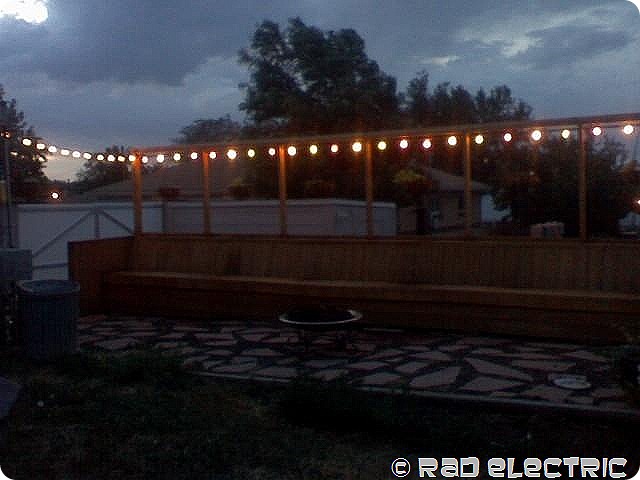
rad1

Custom patio lighting

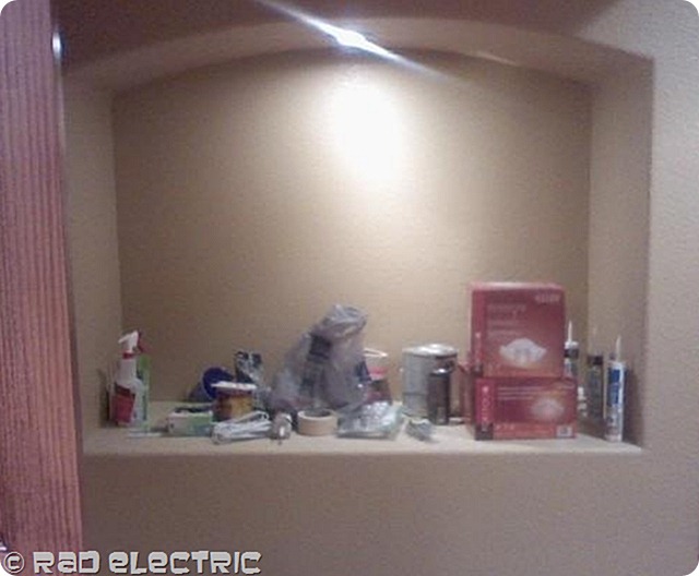
rad3

Fished in niche lighting

rad2

Fireplace lighting

rad4

Low-voltage clean-up

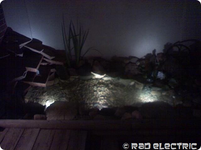
rad5

Pond lighting

rad6

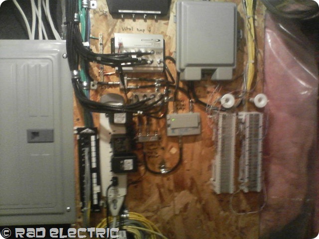
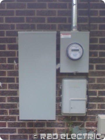
Service change

Filed Under: Gallery ·

Switching Aluminum Wiring to Copper

· by Randy ·

Aluminum wiring, used in some homes from the mid 1960’s to the early 1970’s, is a potential fire hazard. How safe is aluminum wiring? According to the U.S. Consumer Product Safety Commission, fires and even deaths have been reported to have been caused by this hazard. Problems due to expansion, or more likely micro-fretting and arching at the connectors, can cause overheating at connections between the wires and devices (switches and outlets) or at splices. The connections can become hot enough to start a fire without ever tripping a circuit breaker! This is why it is so important for you to change your wiring over from aluminum to copper.

Who needs to worry about switching their wiring from aluminum to copper?

CPSC research shows that homes wired with aluminum wire manufactured before 1972 are 55 times more likely to have one or more connections reach “Fire Hazard Conditions” than are homes wired with copper. “Post 1972: aluminum wire is also a concern. Introduction of the aluminum wire “alloys” in 1972 time frame did not solve most of the connection failure problems. Aluminum wiring is still permitted and used for certain applications, including residential service entrance wiring and single-purpose higher amperage circuits such as 240V air conditioning or electric range circuits. The fire risk from single purpose circuits is much less than for branch circuits. It’s not necessarily because of a “new alloy” as some folks assert. It’s because there are enormously fewer connections (four or six rather than 30 or 40 per circuit) and thus statistically a smaller chance of a connection failure. These connections do still burn up, as indicated by field reports.

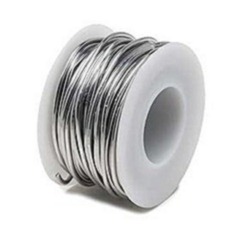
aluminumwire

ALUMINUM WIRING [the history and the fire hazard] on April 28, 1974, two persons died in a home fire in Hampton Bays, New York. Fire officials determined that the fire was caused by a faulty aluminum wire connection at an outlet. Since that tragic accident, the U.S. Consumer Product Safety Commission staff and other government officials have investigated numerous complaints from homeowners throughout the nation who have had trouble with small gauge aluminum branch circuit wiring. The Commission has also had research conducted that shows that homes wired with aluminum wire manufactured before 1972 (“old technology” aluminum wire) are 55 times more likely to have one or more connections reach “Fire Hazard Conditions” than is a home wired with copper.

The hazard investigated by the Commission staff occurs at connections to old technology aluminum wire, such as at outlets or switches or at major appliances such as dishwashers, furnaces, etc. Corrosion of the metals in the connection, particularly the aluminum wire itself, causes increased resistance to the flow of electric current and that resistance causes overheating.

Homes built before 1965 are unlikely to have aluminum branch circuit wiring. Homes built, rooms added and circuits rewired or added between 1965 and 1973 may contain aluminum wiring.

In 1972, manufacturers modified both aluminum wire and switches and outlets to improve the performance of aluminum wired connections. Sale of the old style wire, switches and outlets still on dealers’ shelves however, continued after 1972.

Trouble signs [of overheating aluminum wiring] Signs of trouble in aluminum wire systems include warm-to-the-touch face plates on outlets or switches. Unfortunately, not all failing aluminum wired connections provide such easily detected warning signs aluminum wired connections have been reported to fail without any prior indications or problems.

What the electrician can do [to repair unsafe aluminum electrical wiring] If you had noticed any of the trouble signs, have a qualified electrician determine whether the problem is caused by deteriorating connections to aluminum wiring. DO NOT TRY TO DO IT YOURSELF. You could be electrocuted or you could make the connections worse by disturbing them. If you are not certain whether your home has aluminum branch circuit wiring, you may be able to tell by looking at the markings on the surface of the electric cables which are visible in unfinished basements, attics or garages. Aluminum wiring will have “Al” or “Aluminum” marked every few feet along the length of the cable. (Note- The marking “CU-clad” or “Copper-clad” in addition to the “AI” or “Aluminum” means that the cable uses copper-coated aluminum wire and is not covered by this message.)

If you do have aluminum branch circuit wiring, the Commission suggests that you have a qualified electrician check the system for impending trouble. Remember, you may not have noticed any of the warning signs, but research shows that trouble may develop over time and an electrician may spot potential problems before you notice them.

CAN THE [aluminum wiring] PROBLEM BE FIXED? One method of eliminating the risks associated with old technology aluminum wiring terminations is to eliminate the primary cause; the aluminum wire itself. Depending upon the architectural style of your home and the number and locations of unfinished spaces (e.g., basements and attics), it may be relatively easy to rewire your home. A new copper wire branch circuit system would be installed, and the existing aluminum wire would be abandoned inside the walls. This is the most expensive method of repairing an aluminum wired home; but if you can afford the cost, it is also the best method available. Since it may be impractical to rewire some types of aluminum wired homes (i.e., condominium units), or since rewiring may be prohibitively expensive for some homes (i.e., split-levels with no unfinished areas), the Commission staff attempted to find a repair method which would permit the continued use of existing old technology aluminum wire.

Filed Under: RAD Blog ·

Next Page »

Military Discount

Let us be the first to say thank you for serving our country. As a small token of our gratitude, we would like to offer you a 10% discount when you show us your military ID. Thank you again for all of your hard work in defending the land we call home

Senior Discount

You have worked hard in your life; let us extend a special discount to you. When you mention this website you will receive and additional 10% off of your purchase

Copyright © 2023 | Innovative Child Theme by The Pixelista | Built on the Genesis Framework